When using the Revit API, we often perform tasks involving multiple geometries. For instance, we might compare their positions or identify their intersections. However, it’s important to note that even if these geometries appear close in the Revit 3D space, they could be related to different coordinate systems. In this case, comparing these geometries while referring to their respective coordinates might give us incorrect results.
I once had to write a script that checked whether MEP elements from a linked model had the exact same position as those in the host model. Curiously, even when Revit displayed all elements to be aligned, the script’s results expressed the opposite. I eventually figured out that each model positioned its elements differently in relation to the internal origin, leading to incorrect results. Although, the elements of both models had the same position to the project base point, which explained the visual alignment.
A way of solving similar problems is by using the revit transformations and applying them to the geometries. They allow to convert a geometry’s coordinates from one system to another. Beyond this case, transformations are also useful to simply move a geometry within one same Revit model, with no consideration to multiple coordinate systems.
Before going further, you might want to understand more about Revit transformations. For more insights, please refer to the preceding article : Revit Transformations Made Easy
Moving the solid
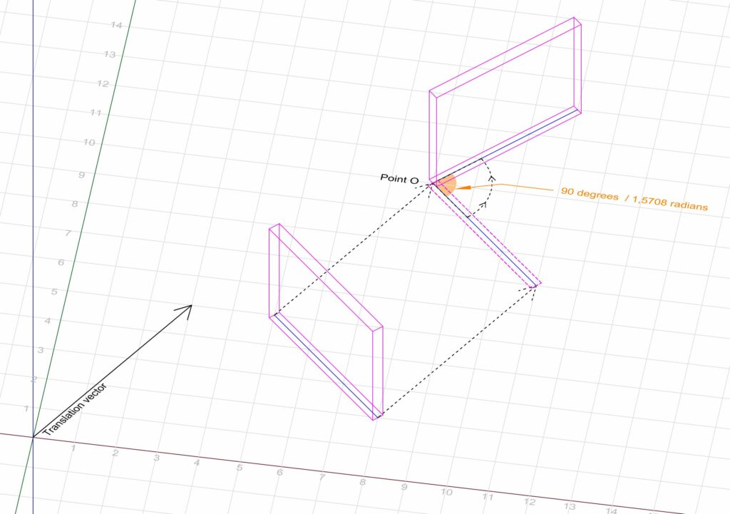
For a better understanding of how transformations are applied to geometries in Revit, let’s consider a simple example : translating and rotating a wall. We begin by defining a method that takes the wall’s geometry as an argument, applies the desired translation and rotation to it, and then returns the resultant geometry. We’ll name this method TransformSolid().
We will be using three classes provided by the Revit API :
- Transform : a class that holds the instructions for moving a point or a geometry in the 3D space.
- Solid : a class that represents the geometric data of any object modeled in Revit.
- SolidUtils : a class that performs multiple operations related to solids, among which the application of transformations using the static method SolidUtils.CreateTransformed().
While this example involves a basic geometry, the same approach can be used for more intricate ones.

    public class Transformations
    {
        public static Solid TransformSolid(Solid wallSolid)
        {
            XYZ translationVector = new XYZ(3, 5, 0);
            XYZ rotationAxis = new XYZ(0, 0, 1);
            XYZ pointO = new XYZ(8, 10, 0);

            double rotationAngle = 1.5707963268; // Unit is in Radian

            // Defining the rotation and translation transformations
            Transform transform_Translation = Transform.CreateTranslation(translationVector);
            Transform transform_Rotation = Transform.CreateRotationAtPoint(rotationAxis, rotationAngle, pointO);

            // Combining the transformations
            Transform transform_TranslationPlusRotation = transform_Rotation.Multiply(transform_Translation);

            // Using the SolidUtils.CreateTransformed() static method to apply the transformation on the solid
            Solid transformedSolid = SolidUtils.CreateTransformed(wallSolid, transform_TranslationPlusRotation);

            return transformedSolid;
        }

    }
Converting the coordinates
So far we have seen how to apply a transformation to a Solid. This same approach is actually used to convert a geometry’s coordinates between two distinct Revit models that have different coordinate systems. The question now is : how do we find the Transform object we need to make such conversion.
In the Revit API, Linked models are represented by two classes : RevitLinkType and RevitLinkInstance. The latter actually provides a method to retrieve the Transform object we seek : RevitLinkInstance.GetTransform(). let’s identify this object as linkModelTransform.
To convert the geometry’s coordinates from the linked model’s system to the host model’s system : we can directly use linkModelTransform as an argument for the SolidUtils.CreateTransformed() method.
To convert the geometry’s coordinates from the host model’s system to the linked model’s system, we must instead use the inverse of linkModelTransform.
An inverse Transform object holds the “opposite” transformations, and is obtained using the linkModelTransform.inverse property.
Conclusion
Beyond the conversion of coordinates from one system to another, the application of transformations to geometries represents a foundation for more complex tasks. Once you begin using them, you quickly understand the freedom and the new possibilities they enable when working with geometric data. Now go and build stuff. Have fun 😉