One of the challenges I encountered with the Revit API was about defining the spatial positions of a model’s elements in relation to each other. I had to consider this issue when automating the control of openings within a wall, as to ensure their positions complied with specific structural constraints.
By default, the Revit API returns a point’s coordinates as related to the internal origin, considered to be the center of the model’s global coordinate system. In my case, however, I wanted the openings’ coordinates to be related to a wall-specific coordinate system. This would make the structural verification algorithms easier to design and program.
The following presents a methodology I have developed and been using to convert coordinates from the model coordinate system to an element-specific one. I will first present the steps of this methodology in terms of geometric operations, then will provide the related C# code.
Before going further, you might want to understand more about Revit transformations. For more insights, please refer to the preceding article : Revit Transformations Made Easy
Coordinates conversion
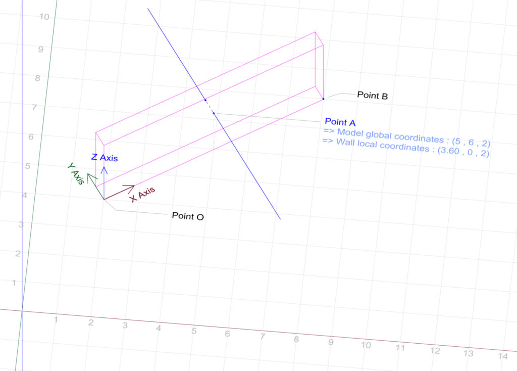
The example we will be using is that of a simple wall. We establish the local coordinate system for this wall using one of its lower corners, PointO, as the origin, with global coordinates of (2, 4, 0). The local coordinate system’s axes align with the wall’s three edges meeting at this point.
PointA is where a horizontal line meets one of the wall’s faces, with global (model) coordinates of (5, 6, 2) and local (wall) coordinates of (3.60 ,0 ,2). Our purpose is to understand how to convert PointA‘s coordinates from the global to the local coordinate system.
Step 1
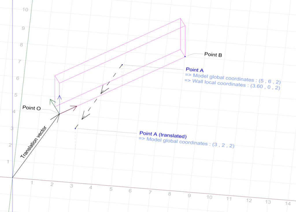
We begin by defining a vector that starts at the model’s internal origin and extends towards Point O. We then define the opposite of this vector, and use it to translate PointA.
Step 2
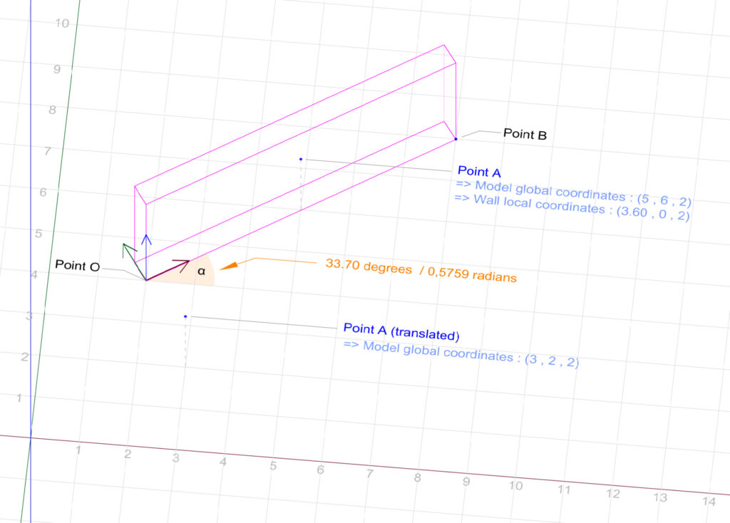
We calculate α : the angle between the wall’s local x-axis and the model’s global x-axis.
Step 3
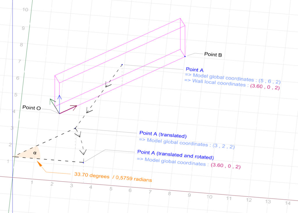
We rotate the translated pointA around the model’s internal origin by the angle α. The result is a point with global (model) coordinates of (3.60, 0, 2). We notice that these coordinates actually match those of PointA when related to the local (wall) coordinate system.
In summary, the process involves defining a local coordinate system related to an element and using transformations to convert global coordinates to local coordinates. Even if we have the freedom to define the origin of the local coordinate system and the orientation of its axes, the logic for converting the coordinates remains consistent.
This process could be expressed programmatically by the following C# code :
public class CoordinatesConverter
    {
        public void ConvertCoordinates()
        {
            XYZ pointA = new XYZ(5, 6, 2);
            XYZ pointB = new XYZ(8, 8, 0);
            XYZ pointO = new XYZ(2, 4, 0);
            XYZ rotationAxis = new XYZ(0, 0, 1);
            XYZ translatedAndRotatedPointA;
            XYZ translatedPointB;

            Transform transform_Translation = Transform.CreateTranslation(pointO);
            Transform transform_invertedTranslation = transform_Translation.Inverse;

            // To calculte alphaAngle we first need to translate pointB. The resulting vector will have the same direction as the wall's x-axis.
            translatedPointB = transform_invertedTranslation.OfPoint(pointB);
            double alphaAngle = translatedPointB.AngleTo(new XYZ(1, 0, 0));

            // Since we want our rotation to be done clockwise, alphaAngle needs to be negative
            Transform transform_Rotation = Transform.CreateRotation(rotationAxis, alphaAngle * -1);
            Transform transform_TranslationPlusRotation = transform_Rotation.Multiply(transform_invertedTranslation);

            translatedAndRotatedPointA = transform_TranslationPlusRotation.OfPoint(pointA);
            // translatedAndRotatedPointA coordinates will be : 3.60, 0, 2
        }
    }