Transitioning from Dynamo scripting to Autodesk® Revit Add-in development introduced me to a higher level of software complexity. It required me to consider various aspects, including database connections, user interface creation, authentication checks, and the organization of multiple C# and XAML files.
Architectural patterns are a good way of managing such complexity. They provide a frame to organise the different components of your add-in, and are valuable in guiding your development process.
In this first article of a three-part series, I will explain the main principles of the pattern I have been using, called the Model-View-ViewModel pattern. In the second part to come, I will present my implementation of this pattern for creating Revit Add-ins.
Software architecture
In simple terms, software architecture is about defining the responsibility and organisation of the main parts of a system or application.
Responsibility means which types of actions and data a software’s part is concerned about, and which it isn’t. Organization means how the software parts are linked and communicate with each others. It is about choosing which information is sent from a part to another, and how this transmission is made possible. It is also about managing the dependencies between these different parts and components.
A good software architecture in my opinion allows you to evolve and maintain software in the easiest and quickest way. For each update you want to make, you need to identify instantly where to intervene. Therefore, the organizing logic of the whole software system should be clear and coherent.
M-V-VM pattern : the layers
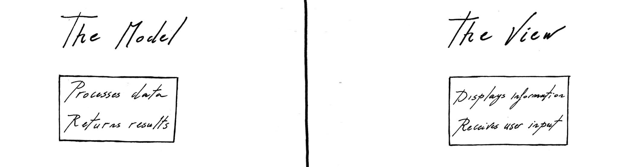
The main purpose of the M-V-VM pattern is to define distinct layers for an application. On one hand, we have the Model representing (or modeling) the business data and logic. On the other hand, we have the View representing the graphical user interface.
This ensures that each part of our project’s codebase has a clear main responsibility, depending on the layer it belongs to. None of these two layers ‘know’ about the other : the code of the Model doesn’t relate or intervene upon the code of the View, and vice-versa.
Such organisation refers to the separation of concerns principle. Besides making our application’s design and maintenance easier, it also reduces the risk of errors. Since the layers are decoupled, you won’t be breaking the UI code when updating the add-ins algorithms.
Then comes the ViewModel : the intermediate layer between the Model and the View :
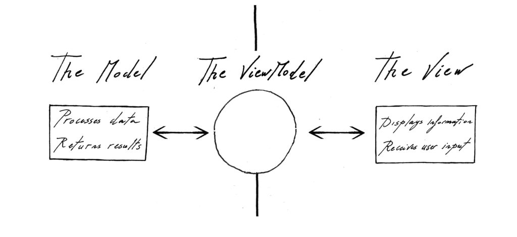
The ViewModel‘s responsibility is to model the View by storing and managing all the collected or displayed data. This data can either be the input to be processed by the Model‘s methods, or the output generated by these methods.
The ViewModel serves as an interface for the View to communicate with the Model while maintaining the separation of concerns principle. This interface stores the results of the Model‘s logic but does not contain the logic itself. However, it may include functionalities that filter or organize the information for display.
M-V-VM pattern : the data flow
To help us better understand how the three layers of an M-V-VM application communicate, let’s consider a simple example. Let’s say we want to make an Add-in that returns the number of elements of a certain category contained in a Revit file.
The Add-in would work following these steps :
- The View displays the available categories within the Revit file
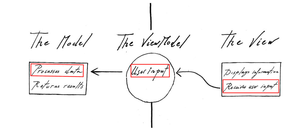
- The user selects one of these categories using the View
- The ViewModel “listens” to the View and records the user’s choice
- The user presses a button in the View to count elements in the chosen category.
- The ViewModel records the user’s request and instructs the Model to perform the required action.
The next steps will be:
- The Model accesses the Revit file, and filters all its elements of the chosen category
- It returns this processed data to the ViewModel, which records it
- The ViewModel then notifies the View of its update
- The View “listens” to the ViewModel and displays the elements requested by the user
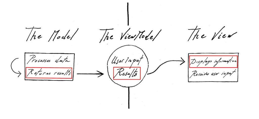
In summary, the M-V-VM pattern enables bidirectional data flow, with information processed by the Model reaching the View for user interaction and instructing the Model in return. This allows the graphical user interface to remain interactive and responsive.
Conclusion
The M-V-VM pattern offers a clear frame for designing software. It drives you to define the responsibility of your application’s components, and gives you guidelines on how to link them.
I think It’s an interesting pattern for managing a project’s complexity in the long run, addressing the evolution of both the algorithms and the graphical user interface.
In the following article, I will share my implementation of the M-V-VM pattern for creating Autodesk Revit Add-ins using C# and WPF. Stay tuned 😉