As a Revit API developer, the Model-View-ViewModel pattern is essential to learn if you’re looking to build more complex and scalable add-ins. In the first article of this three-part series, I have presented this pattern’s main principles and key points. I propose now to share an M-V-VM based implementation I use for making Revit Add-ins.
In this second article, we will build a simple add-in to explain the M-V-VM key concepts in a clear way. We will focus on how to set up the add-in’s main structure, and how to make the View layer displays the data processed by the Model layer. The third and final part to come will focus on how to collect and process the user’s input using M-V-VM.
We will use Visual Studio, C#, the XAML markup language and the WPF framework. If you are completely new to Revit’s add-in development, I would recommend you first watch the Revit + WPF tutorial series by Abderrahmane Mazri. They provide a clear explanation about how to set up a Revit add-in project.
The entire project setup used in this series can be retrieved on GitHub.
Setting up the add-in’s main parts
Let’s start by introducing the context of our add-in project. In Revit, an element has multiple parameters, each of them being either a family, type, or instance parameter. For updating a wall’s width, for example, you need to update the wall’s type which holds this property.
We want to build a simple add-in that retrieves the width of each of the wall types available in a Revit project file. It should display these types to the users for selection, and then return the related width.
We start by creating our add-in’s project in Visual Studio, and set the following structure :
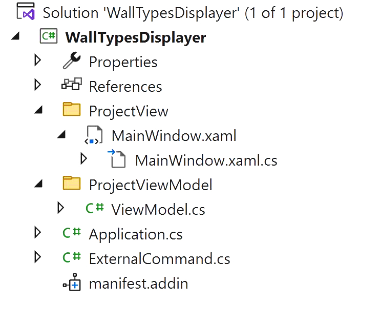
The ExternalCommand class enables our add-in to communicate with the Revit software. Its ExternalCommand.Execute() method is our add-in’s entry point. It is the place where the Revit API provides us with the data contained in the Revit project file.
Within this method, we will later retrieve the Document class. It contains the Revit project data, and more specifically, the Revit project wall types we need. Therefore, the Document class belongs to the Model layer.
As its name suggests, the ViewModel class represents the intermediate layer between the Model and the View. It will reference the data stored in the Document object, which it will present to the add-ins’ window for display.
Finally, we create a WPF window named MainWindow, composed of both a XAML file and a C# file (code behind). Both of these files logically belong to the View layer.
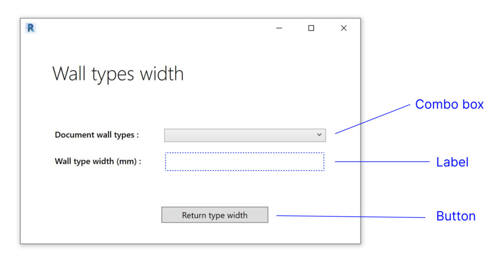
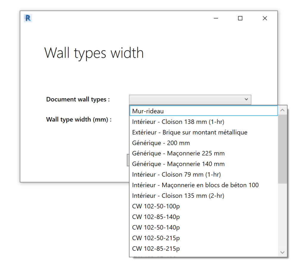
We want to keep this window very simple. It contains a combo box control for displaying the available wall types, a button for confirming and processing the selection and a label that displays the returned wall type’s width.
Defining the add-in’s main layout
So far we have defined and created the add-in’s main components. We have described three classes, each belonging to a different layer of the M-V-VM pattern. Yet, no links have been set between them for the information to be exchanged.
How would the ViewModel object retrieve and store the wall types from the Document object ? And how would they be transmitted from the ViewModel to the WPF window ?
We can use the object-oriented concept of aggregation to set up the links between these objects. Aggregation means that an object A (the container) “has” or “owns” an object B (the part). Object A can therefore exploit the data or the functionality implemented by object B.
The following graphic shows how our add-in could be structured using the aggregation concept :
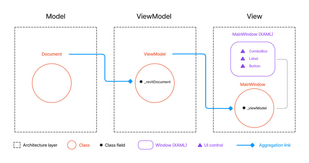
Following this principle we define the MainWindow object as a container for the ViewModel object, storing it in its _viewModel field. Our Window will then exploit the states of the ViewModel object by displaying them to the user.
The ViewModel object by itself is a container to the Document object. This way it will retrieve and store the data contained within our Revit project, before providing it to the add-in’s WPF window.
By making the MainWindow the principal container, we establish a simple layout that allows the user to visualise and interact with the data contained in the Revit project file.
Let’s now dive into the code of each class to better understand the details of the implementation :
The MainWindow class (the window’s C# code behind)
namespace WallTypesDisplayer
{
    public partial class MainWindow : Window
    {
        private ViewModel _viewModel;

        public ViewModel ViewModel { get { return _viewModel; } }

        public MainWindow(ViewModel vModel)
        {
            InitializeComponent();

            this._viewModel = vModel;
            DataContext = this._viewModel;
        }
    }
}
In its constructor, the MainWindow class establishes the aggregation link with the ViewModel object and defines it as its DataContext. The data context means the source of the data displayed by the window.
The ViewModel class
namespace WallTypesDisplayer.ProjectViewModel
{
    public class ViewModel
    {
        private Document _revitDocument;
        public Document RevitDocument
        {
            get { return _revitDocument; }
            set { _revitDocument = value; }
        }

        public ViewModel(Document rvtDocument)
        {
            this.RevitDocument = rvtDocument;
        }
    }
}
The ViewModel class uses its constructor to establish the aggregation link with the Document object.
The ExternalCommand class (entry point of the Add-in)
namespace WallTypesDisplayer
{
    [TransactionAttribute(TransactionMode.Manual)]
    public class ExternalCommand : IExternalCommand
    {
        public Result Execute(ExternalCommandData commandData, ref string message, ElementSet elements)
        {
            Document revitDocument = commandData.Application.ActiveUIDocument.Document;
            ViewModel viewModel = new ViewModel(revitDocument);
            MainWindow mainView = new MainWindow(viewModel);

            mainView.ShowDialog();
            return Result.Succeeded;
        }
    }
}
Once we have defined the MainWindow and ViewModel classes, we instantiate them following the aggregation principle within the add-in’s entry point and launch the add-in’s window. As a reminder, commandData is the object containing all the data provided by the Revit API.
Filtering and displaying the wall types
Now that we set up the add-in’s main layout, we need to display the Revit project’s wall types in the windows’s combo box. Therefore, we need to figure out two things : how to extract a list of the wall types from the Document class (Model), and how to link these types to the window’s combo box (View).
We will first create a new class named DocumentTypesExtractor and implement a DocumentTypesExtractor.ExtractWallTypes() method. As its name indicates, it returns a list of WallType objects contained in a Document object. This class processes elements of the Revit project database and logically belongs to the Model layer.
Following the add-in’s layout logic, we attribute a new field to the ViewModel class : _revitDocumentWallTypes. This field will store the list of the WallType objects as returned by DocumentTypesExtractor.ExtractWallTypes().
Finally, we will set a data binding between the _revitDocumentWallTypes field and the window’s combo box. This will enable the window to read and display the collected wall types.
We may then update our layout graphic as the following :
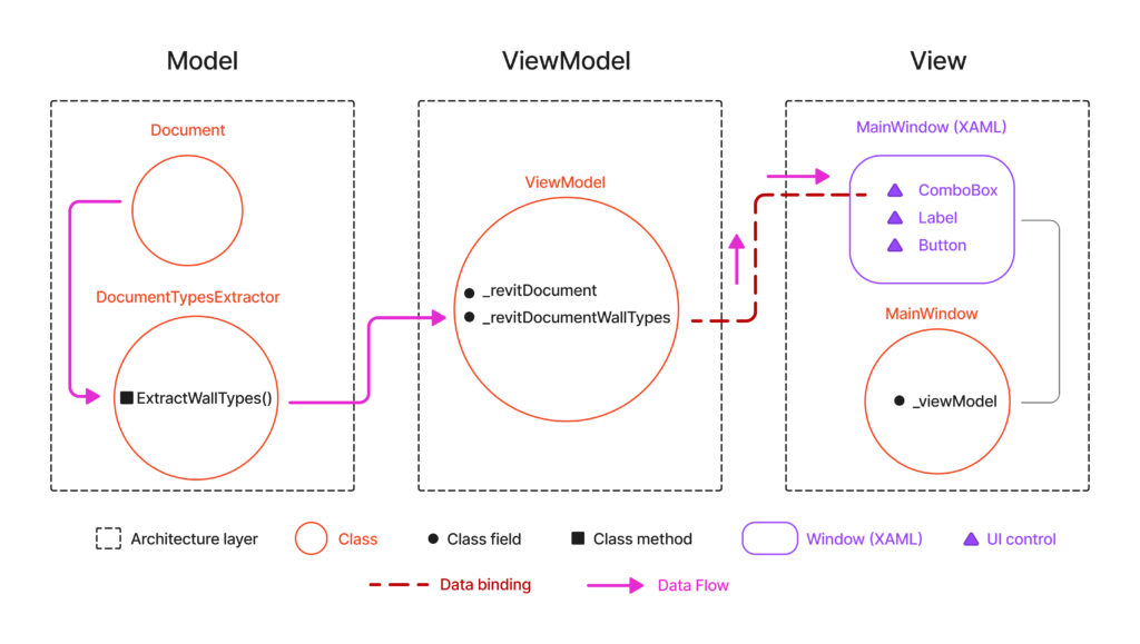
Data binding in WPF is a fundamental technique that establishes a connection between a WPF control (UI element) and a corresponding field in a class. Like a bridge, it allows the data to flow between these two elements for automated update and display.
The layout graphic gives an overview of our add-in’s architecture and data flow. It shows how the Model, the ViewModel and the View communicate in order to retrieve, store and display the project’s wall types.
Let’s now focus on the implementation details of our add-in’s update.
The DocumentTypesExtractor class
namespace WallTypesDisplayer.Model
{
    public class DocumentTypesExtractor
    {
        public static List<WallType> ExtractWallTypes(Document rvtDocument)
        {
            IList<Element> documentWallTypes = new FilteredElementCollector(rvtDocument).OfClass(typeof(WallType)).ToElements();
            return documentWallTypes.Cast<WallType>().ToList();
        }
    }
}
To keep the implementation simple, we define DocumentTypesExtractor.ExtractWallTypes() as a static method. This means we won’t need to instantiate a DocumentTypesExtractor object to execute it.
Note that while the FilteredElementCollector class returns a list of Element objects, these elements are, in fact, of the WallType type. This aligns with the inheritance hierarchy in the Revit API : the WallType class is a specialized type that inherits from the more general Element class.
To ensure the method’s return type accurately reflects this, a type cast is used, explicitly converting the elements to WallType objects. This cast reinforces the method’s purpose and provides a clear and coherent representation of the data it retrieves
The ViewModel class (Updated)
namespace WallTypesDisplayer.ProjectViewModel
{
    public class ViewModel
    {
        private Document _revitDocument;
        public Document RevitDocument
        {
            get { return _revitDocument; }
            set { _revitDocument = value; }
        }

        private List<WallType> _revitDocumentWallTypes;
        public List<WallType> RevitDocumentWallTypes
        {
            get { return _revitDocumentWallTypes; }
            set { _revitDocumentWallTypes = value; }
        }


        public ViewModel(Document rvtDocument)
        {
            this.RevitDocument = rvtDocument;
            this.RevitDocumentWallTypes = DocumentTypesExtractor.ExtractWallTypes(this.RevitDocument );
        }
    }
}
We enhance the ViewModel class by introducing the _revitDocumentWallTypes field. Subsequently, we employ the class constructor to assign this field with the result obtained from the DocumentTypesExtractor.ExtractWallTypes() static method. This configuration retrieves the data from the Model and stores it in the VewModel while keeping the code simple.
The window’s XAML code
<Window x:Class="WallTypesDisplayer.MainWindow"
             xmlns="http://schemas.microsoft.com/winfx/2006/xaml/presentation"
             xmlns:x="http://schemas.microsoft.com/winfx/2006/xaml"
             xmlns:mc="http://schemas.openxmlformats.org/markup-compatibility/2006"
             xmlns:d="http://schemas.microsoft.com/expression/blend/2008"
             xmlns:local="clr-namespace:WallTypesDisplayer"
             mc:Ignorable="d"

             Height= "330"
             Width="500"
>
    <Grid>
        <ComboBox ItemsSource ="{Binding RevitDocumentWallTypes}" DisplayMemberPath="Name" HorizontalAlignment="Left" Height="19" Margin="206,130,0,0" VerticalAlignment="Top" Width="232"/>
        <Label HorizontalAlignment="Left" Height="26" Margin="206,163,0,0" VerticalAlignment="Top" Width="232" Foreground="Black" FontWeight="SemiBold"/>
        <Button Content="Return type width" HorizontalAlignment="Left" Height="23" Margin="202,242,0,0" VerticalAlignment="Top" Width="153" RenderTransformOrigin="0.5,0.5"></Button>
        <TextBlock HorizontalAlignment="Left" Height="19" Margin="49,130,0,0" TextWrapping="Wrap" VerticalAlignment="Top" Width="136" FontWeight="DemiBold"><Run Text="Document "/><Run Language="fr-fr" Text="w"/><Run Text="all "/><Run Language="fr-fr" Text="t"/><Run Text="ypes"/><Run Text=" :"/></TextBlock>
        <TextBlock HorizontalAlignment="Left" Height="45" Margin="45,30,0,0" TextWrapping="Wrap" VerticalAlignment="Top" Width="294" FontSize="28" FontWeight="Light"><Run Text="W"/><Run Text="all"/><Run Text=" types"/><Run Text=" "/><Run Language="fr-fr" Text="width"/></TextBlock>
        <TextBlock HorizontalAlignment="Left" Height="18" Margin="49,168,0,0" TextWrapping="Wrap" VerticalAlignment="Top" Width="136" FontWeight="DemiBold"><Run Text="Wall "/><Run Language="fr-fr" Text="t"/><Run Text="ype"/><Run Text=" width "/><Run Text="(mm)"/><Run Text=" "/><Run Text=":"/></TextBlock>

    </Grid>
</Window>
As we’ve seen previously, the add-in’s window is linked to the ViewModel object by specifying it as its data context (in the windows’s code behind), and by using a data binding link. More precisely, the window’s combo box should display the content of the ViewModel‘s _revitDocumentWallTypes field.
The data binding is made possible by assigning the value “{Binding RevitDocumentWallTypes}” to the ItemsSource property in the ComboBox markup. Note that in WPF, the windows’s data is always bound to a class’ public property. RevitDocumentWallTypes is here a reference to the ViewModel.RevitDocumentWallTypes public property, which by itself encapsulates the ViewModel._revitDocumentWallTypes private field.
Finally, a WallType object by itself is composed of multiple data layers. Therefore, we need to inform the window which of these layers is to be displayed. In this case, we want to show the user the names of the available wall types, and will attribute the value “Name”, a string type property of the WallType class, to the combo box’s DisplayMemberPath property.
Having set this implementation, our add-in’s window will display the Revit project’s available wall types in its combo box.
Conclusion
In this second article part, we’ve explored the implementation of the M-V-VM pattern fundamental principles for Autodesk Revit add-in development. We’ve detailed the design choices and focused on the data flow from the Model to the ViewModel and the View.
In the upcoming third and final part of this series, we’ll focus on user interaction. We’ll see how users can select their desired wall type, how this choice is processed, and how the result is presented. Hopefully, you will have an overall view about the basic implementation of the MVVM pattern for making Revit add-ins. Stay tuned 😉